
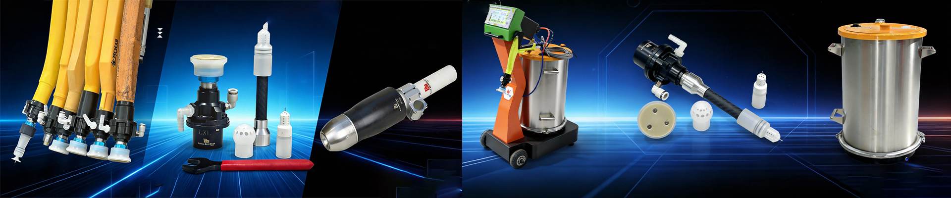
Rotary Cup Powder Coating Parameters: What to Adjust First
Do not use voltage to compensate for a problem you have not located. A painted hanger, an unstable powder feed or a changing spray distance can all make a sound rotary cup system look badly adjusted. Turning up electrostatics may improve one test part while leaving the cause untouched.
For a repeatable setup, work from the physical process toward the electrical settings. Check the cup, pump, hose and air supply; restore reliable grounding; set distance and angle; stabilize powder feed; shape the cloud with cup speed and air; then tune voltage and current. Judge the result on actual production parts, not only on a flat test panel.
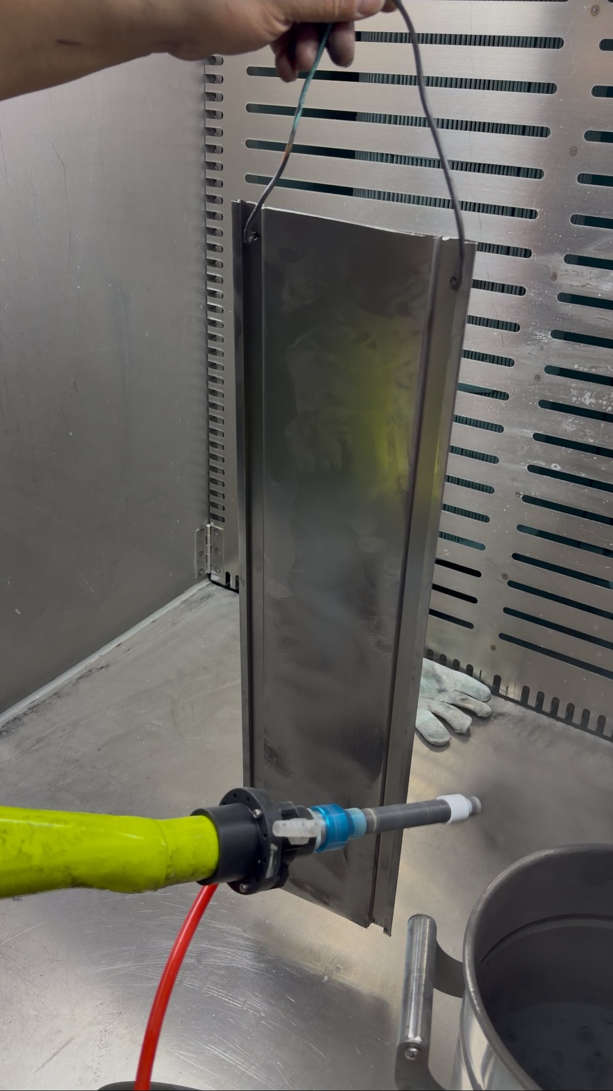
Quick Check: What Should You Adjust First?
| What You See | Check First | Do Not Assume |
|---|---|---|
| Powder barely builds on the part | Hanger contact, workpiece grounding and powder delivery | That the voltage is too low |
| Film varies across the same part | Spray distance, angle and movement path | That cup speed alone will correct it |
| Edges or recesses remain thin | Grounding, part geometry and whether the powder cloud reaches the area | That more electrostatic force always helps |
| Powder cloud pulses or drifts | Pump, hose, air supply and fluidization | That an electrical adjustment will stabilize feed |
| Film is heavy but critical areas are still bare | Powder feed, pattern width and part dwell time | That adding still more powder solves coverage |
The Tuning Order for a Rotary Cup Line
1. Make the powder path mechanically stable
Inspect cup cleanliness, pump condition, hose routing, compressed-air supply and powder fluidization. A dirty cup or irregular feed changes the cloud before any electrical setting can help. If the output surges, find that cause first. Record the powder type, condition and reclaim ratio so a later powder change is not mistaken for a machine-setting failure.
2. Verify grounding at the workpiece
Check hanger contact points and measure grounding resistance from the workpiece through the hanger to earth. Coating buildup on hangers can cause low deposition, uneven film, unstable attraction and poor edge coverage. Clean or repair the contact path before raising voltage. A higher setting cannot make an unreliable electrical connection reliable.
3. Set distance and spray angle for the actual part
Keep cup-to-part distance as consistent as the workpiece and motion path permit. Too close can create heavy build, uneven film and back-ionization risk; too far can reduce deposition and edge coverage. Confirm that the powder cloud can physically reach the faces and recesses you expect it to coat. If a narrow groove is inaccessible, changing a number on the control panel is not a substitute for checking geometry, position or nozzle choice.
4. Stabilize powder feed before increasing it
Set a steady feed, then change it gradually while watching film build. Too little powder can prompt operators to over-correct with voltage or distance. Too much can waste powder, produce heavy film and hide the original coverage problem. Compare results on the same part family rather than making several changes at once.
5. Shape the pattern with cup speed and air
Cup speed changes cloud shape and powder distribution. If it is too low for the setup, atomization or distribution may be uneven; if it is too high, powder may spread too widely or useful deposition may fall, depending on booth airflow and spray distance. Where the equipment provides shaping or atomizing air adjustment, tune it with cup speed to suit the part. There is no transferable speed setting that fits every powder, booth and workpiece.
6. Tune voltage and current limit last
Only after the physical setup and powder cloud are stable should you adjust electrostatic settings. More attraction is not always better: excessive electrical force can worsen recessed-area coverage, back ionization or surface texture. Tune voltage and current limit together with the established distance and powder output, and keep a record of the combination used for each part family.
7. Validate on production parts
Check film thickness and appearance on representative parts, including the areas that usually fail. Record the workpiece, powder, line speed, hanger spacing, spray distance and angle, feed, cup speed, air settings, voltage, current limit and booth conditions alongside the result. A setting is a starting point until it survives the real line, the real geometry and the required quality check.
When Parameter Changes Have Reached Their Limit
If the conveyor runs too fast for the part geometry, the available pass time may be inadequate even with a stable gun. Pattern width, pass overlap and dwell time have to match the target film build. Likewise, a narrow recess may remain hard to coat if the cloud cannot reach it or the part is poorly grounded. In those cases, revisit line speed, path, part presentation or nozzle selection before continuing to turn up electrical settings.
You may not need a new machine. If cleaning hangers, repairing powder delivery or correcting the path makes the result stable, keep the equipment and document the process. If the physical conditions are controlled but difficult geometry still fails, test a different configuration on your own parts before deciding on an equipment change.
Frequently Asked Questions
Why won't powder stick even when I increase the voltage?
Check the grounding path from the workpiece through the hanger, then confirm that powder feed and distance are stable. Poor contact and weak delivery can look like low voltage. Increasing the setting before those checks can conceal the problem without fixing it.
Should I adjust powder feed or kV first when film thickness is low?
First confirm grounding, distance and whether powder is arriving steadily. If feed is genuinely low, increase it gradually and measure the result. Tune voltage and current only after delivery is stable; otherwise you cannot tell which change helped.
What rotary cup speed should I use for a new powder?
There is no single speed that transfers across equipment, powder, booth airflow and part distance. Start from the equipment's suitable setup, observe the cloud and film on a representative part, and adjust cup speed and shaping air together. Keep the result only after a test spray meets your quality target.
Why are my flat faces coated but the edges and recesses are thin?
Verify hanger contact and check whether the spray angle and distance let the cloud reach those areas. More electrical force can make recessed coverage worse. If position and grounding are sound, test a nozzle or process configuration better matched to the geometry.
Why does film thickness change from one part to the next on the same line?
Compare part position, hanger spacing, movement path, distance, line speed and powder output between the affected parts. A changing physical condition should be corrected before electrical settings are revised. Map thickness on representative parts so you can see whether the variation follows the line or the workpiece shape.
Can a new rotary cup gun fix unstable powder output?
Not if the instability comes from a worn pump, blocked hose, inconsistent air supply or poor fluidization. Repair and stabilize those first. Consider different equipment only after the process is controlled and a test on your own parts shows a remaining limitation.
Still Unsure Which Setting to Change on Your Line?
Send us workpiece photos and dimensions, your powder type, current setup, line speed, film-thickness readings and the specific area that fails. We can help separate a grounding or feed problem from a pattern or geometry limitation, including when you do not need to replace your equipment.
When the answer is not clear from the data, we can arrange a test spray on your own parts before you commit to a new setup.
- Email: jerry@qxdcoating.com
- WhatsApp: +1 646 371 8844
- Related: Rotary Cup Nozzle Selection Guide
- Products: Rotary Cup Powder Coating Equipment