
Powder Coating Aluminum Profiles: Better Coverage for Grooves, Slots, and Heat-Sensitive Parts
Powder coating aluminum profiles is rarely difficult on the broad, open faces. The real production challenge is achieving a consistent finish across the complete cross-section: narrow grooves, T-slots, screw channels, drainage paths, sharp lips, internal corners, cut ends, and thin walls. These features can create light coverage in recessed areas while exposed edges collect too much powder.
Aluminum profiles also respond to heat differently from heavy steel fabrications. Long, thin extrusions reach temperature quickly, while reinforced sections, brackets, and thick junctions may heat more slowly. If seals, plastic inserts, adhesives, thermal breaks, or preassembled components are present, the allowable oven cycle may be limited by the most heat-sensitive material in the assembly.
A reliable process therefore needs more than a higher gun setting. It starts with substrate preparation and grounding, then combines suitable hanging, a recess-first spray sequence, controlled powder delivery, and a cure schedule based on the actual part metal temperature.
Why Aluminum Profile Geometry Creates Uneven Coverage
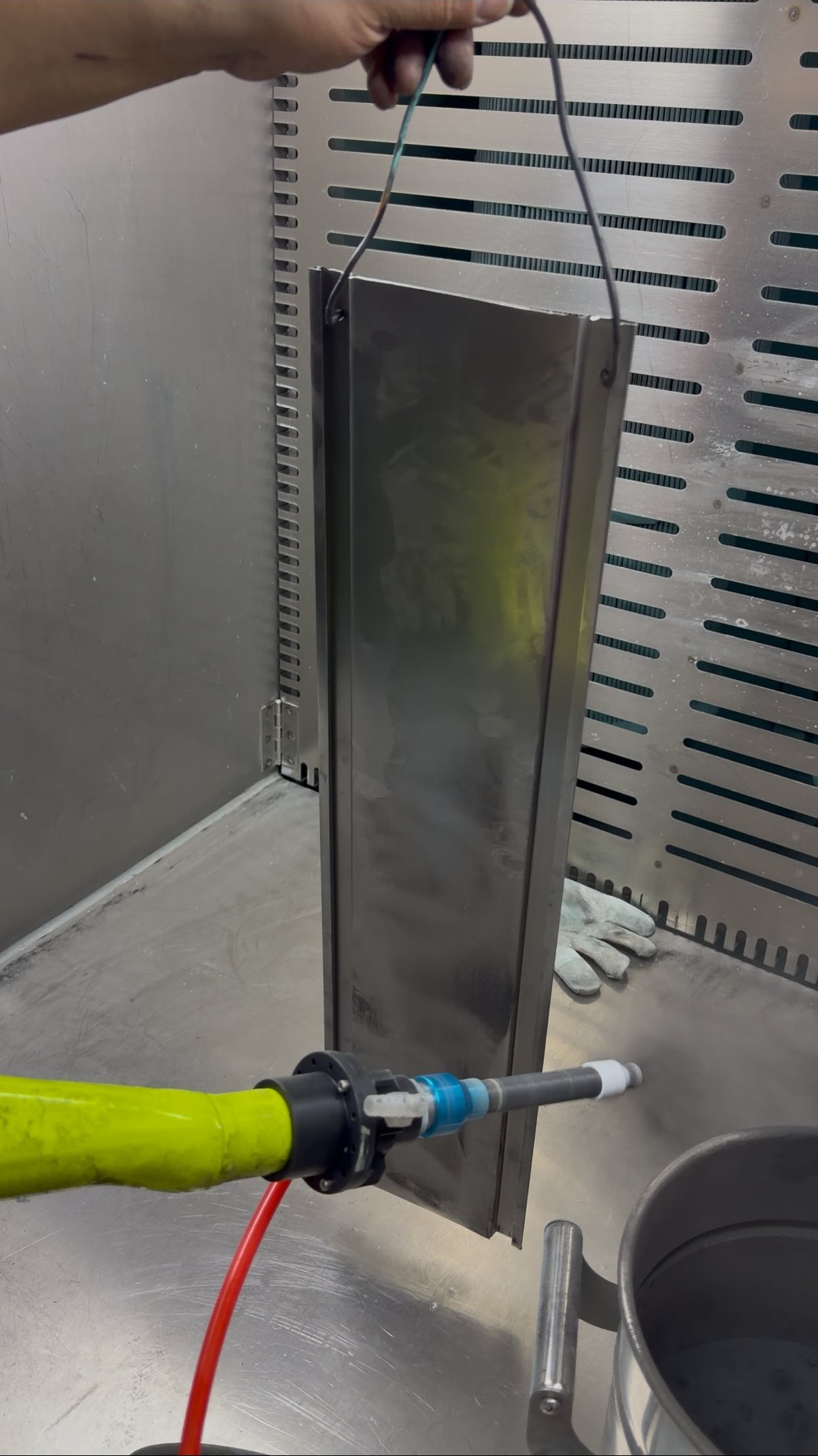
An extrusion can look simple from the front while containing several coating zones. The outer face is easy to reach, but a slot may be shielded by two lips, a screw channel may have a narrow opening, and a deep groove may act like a continuous internal corner. Electrostatic field lines concentrate around exposed edges and convex surfaces, so charged powder tends to build there before enough reaches the bottom and sidewalls of the recess.
This produces a familiar group of defects:
- Thin groove bottoms: the visible face is covered, but the deepest part of the channel remains light.
- Heavy edge build: sharp lips and external corners attract powder first and become rough or overbuilt.
- Shadowing: hooks, adjacent profiles, brackets, or the profile itself block the spray path.
- Uneven gloss or color: inconsistent film thickness and part temperature create a different appearance across the section.
- Pinholes or adhesion loss: contamination, trapped moisture, or incomplete pretreatment remains in channels and cut ends.
The first step is to identify which zone is failing. Increasing powder output without locating the actual cause usually makes the exposed surfaces heavier while the recess remains undercoated.
Prepare the Aluminum Before Adjusting the Gun
Powder cannot compensate for poor pretreatment. Aluminum profiles may carry extrusion lubricant, handling oil, polishing compound, oxide, machining residue, marking ink, or moisture trapped in channels. Clean the complete section, including cut ends, holes, T-slots, and areas hidden by temporary fixtures.
The pretreatment system should match the alloy, service environment, finish specification, and chemical supplier's validated process. Control cleaner concentration, rinse quality, conversion treatment, and drying according to the approved production procedure. Avoid treating one alloy or surface condition as representative of every profile family. Mill-finish, anodized, machined, cast, and previously coated aluminum can require different preparation.
Dry Channels and Hollow Sections Completely
Water can remain in narrow slots or hollow sections after rinsing. When the part enters the oven, trapped moisture or chemistry can escape through the uncured powder and cause pinholes, craters, or local adhesion problems. Orient profiles so liquids drain, use clean drying air where appropriate, and confirm that recesses are dry before coating.
Ground Every Profile Through Clean Contact Points
Long aluminum profiles often hang securely while making weak electrical contact through coated hooks or oxidized rack points. Poor grounding makes powder attraction unstable and encourages operators to compensate with more voltage or more powder. The result can vary from one part to the next even when the control-panel settings are unchanged.
Use clean metal-to-metal contact at a location that will not compromise the visible finish. Check the electrical path through the hook, rack, conveyor, and profile. For batches of several profiles, do not assume the first part proves that every part is grounded. Rack maintenance should be scheduled before buildup becomes a quality problem.
Hang Profiles So Grooves and Slots Stay Accessible
Part presentation determines whether the gun can approach the recess axis. If profiles are packed too closely, one extrusion masks the next and the powder cloud is forced across the slot opening instead of into it. Maintain consistent spacing and orient the difficult feature toward an accessible gun path.
For manual coating, leave room for the operator to reach both sides and change the attack angle. For automatic lines, review gun height, reciprocator stroke, conveyor speed, and the orientation of each profile family. A setup designed for a flat face may miss a downward-facing groove or a channel hidden behind a flange.
Separate Easy Faces From Difficult Features
Do not treat the extrusion as one flat surface. Plan the coating route by feature: deep groove, narrow slot, sidewall, external face, rear face, and cut end. This makes the spray sequence repeatable and prevents easy surfaces from becoming fully charged before recessed areas receive enough powder.
Coat Grooves and Slots Before Broad Exterior Faces
A recess-first sequence is usually more reliable than coating the visible face first. Once the exposed surfaces and lips are heavily loaded, the electrostatic field can make penetration into the channel even more difficult.
- Confirm that the profile is clean, dry, and grounded.
- Approach the deepest groove from an angle aligned with the channel opening.
- Apply a light pass to one sidewall and the groove bottom.
- Change angle and coat the opposite sidewall.
- Coat narrow slots and screw channels with controlled, short passes.
- Finish the broad exterior faces with normal overlapping strokes.
- Inspect the groove bottom, lips, cut ends, and reverse side before curing.
For symmetrical profiles, coating from two directions helps reach both sidewalls. Long continuous channels may need a steady pass parallel to the profile rather than repeated perpendicular sweeps across the opening.
Adjust Powder Delivery Before Raising Voltage
When a slot looks light, raising voltage can strengthen attraction at the outer lips rather than at the groove bottom. Excessive powder output can also flood the opening, increase turbulence, and create heavy edge build. Start with a stable, moderate powder cloud and adjust one variable at a time.
Useful process observations include:
- If powder collects on the lips but not inside the slot, reduce electrostatic intensity and change the gun angle.
- If a dense plume passes across the opening, reduce output or conveying air and align the spray with the recess.
- If coverage varies between identical profiles, check grounding and rack contact before changing settings.
- If the groove is covered but the exterior is thin, use separate recess and finish passes rather than one compromise setting.
- If texture becomes rough on exposed faces, check total film build and back-ionization before adding more powder.
Record successful settings by profile family. Groove depth, opening width, wall thickness, powder chemistry, color, reclaim ratio, booth airflow, and line speed can all change the best setup.
Manage Thin Sections and Heat-Sensitive Assemblies
A powder coating oven must deliver the powder supplier's specified cure at the metal surface. Oven air temperature alone does not prove that the profile has reached the required condition. Use a validated temperature profile for representative parts and measure actual part metal temperature when establishing the process.
Thin aluminum walls can heat and cool quickly. Heavy brackets, doubled sections, and thick joints may lag behind. A single rack can therefore contain hot and cool zones even when every part enters the same oven at the same time. Grouping parts with similar thermal mass improves consistency.
If the profile contains thermal breaks, plastic inserts, seals, adhesives, labels, bearings, electronics, or other preassembled components, confirm their temperature limits before coating. Remove sensitive items when the product design allows, mask protected surfaces, or select a qualified low-bake powder and validated cure schedule. Never shorten the cure only to protect an insert unless the coating supplier confirms that the film still receives the required cure.
Control Film Build on Edges and Functional Features
Profiles often contain functional surfaces that must remain dimensionally controlled: sliding tracks, gasket channels, screw seats, mating faces, grounding points, and drainage openings. Heavy powder can bridge narrow gaps or interfere with assembly.
Define which areas need full cosmetic coverage, which require corrosion protection, and which must be masked or kept within a film-build limit. Use suitable plugs, tapes, caps, or reusable masks where necessary. Inspect critical dimensions after cure as part of the production control plan, not only during the first sample.
Practical Troubleshooting Table
| Observed problem | Likely cause | First checks |
|---|---|---|
| Groove bottom remains thin | Faraday shielding, poor angle, or outer faces coated first | Use a recess-first pass, reduce electrostatic intensity, align with the channel |
| Heavy powder on slot lips | Excessive voltage, current, output, or dwell time | Lower the recess setting and use lighter angled passes |
| Random light areas between profiles | Weak grounding or inconsistent rack contact | Clean hooks and verify continuity for every hanging position |
| Pinholes near channels or cut ends | Trapped moisture, contamination, or outgassing | Review cleaning, rinsing, drainage, drying, and pre-bake requirements |
| Gloss or color varies along the profile | Uneven film build or part metal temperature | Check gun overlap, line loading, oven profile, and thermal mass |
| Assembly does not fit after coating | Excess film on tracks, threads, or mating surfaces | Improve masking and define film-build limits for functional areas |
Quality Checklist Before Production Release
- Confirm alloy, surface condition, pretreatment route, and powder compatibility.
- Verify drainage and complete drying in slots and hollow sections.
- Check grounding through every rack position.
- Standardize profile orientation and spacing.
- Coat grooves, slots, and internal corners before broad faces.
- Record separate recess and finishing settings when needed.
- Measure film build at representative easy and difficult locations.
- Validate cure using actual part metal temperature.
- Confirm temperature limits for inserts, seals, adhesives, and assemblies.
- Inspect masked and functional surfaces after cure.
When a Rotary Cup Powder Gun Can Help
Profiles with repeated grooves and slots can be sensitive to a concentrated pneumatic stream. A rotary cup powder gun produces a distributed powder cloud that can be directed along the channel with less impact on the nearest edge. This can make it easier to coat sidewalls and recesses without flooding the exposed face.
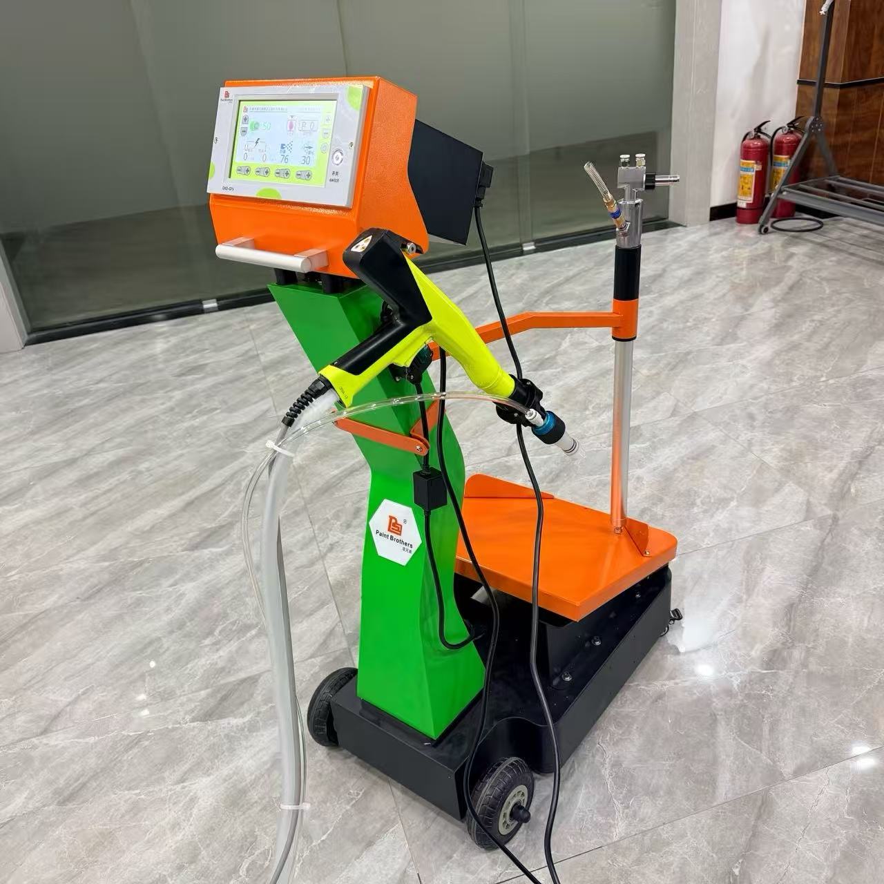
The equipment still has to be matched to the workpiece, powder, booth, and production method. QXD / Paint Brothers can evaluate sample aluminum profiles using the Q7 handheld electrostatic powder coating gun and compare nozzle choice, gun angle, recess settings, film build, and cure requirements.
For the underlying electrostatic behavior, read How to Solve the Faraday Cage Effect in Powder Coating Deep Corners. For broader operating technique, see How to Powder Coat Internal Corners and Recessed Areas. You can also review the Q7 handheld powder coating gun for complex profiles.
Final Thoughts
Better powder coating on aluminum profiles comes from treating every cross-section as a set of different coating zones. Clean and dry the complete profile, maintain reliable grounding, give the gun access to the recess axis, coat difficult features first, and validate the oven cycle using actual part metal temperature.
If your production includes window and door extrusions, curtain-wall profiles, channels, rails, lighting frames, heat-management parts, or other slotted aluminum sections, contact QXD / Paint Brothers. Send profile drawings or photos, groove dimensions, powder details, line speed, and the areas that fail inspection. We can recommend a practical setup or arrange a sample spray test.